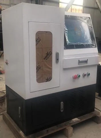
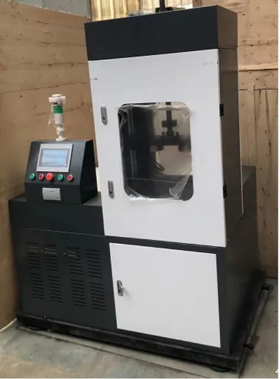
Tpj-W10 Cutomized Shock Absorber Spring Tension Fatigue Testing Machine
Fatigue Testing Machines
Overview
Project:
TPJ-W10 Shock Absorber Demonstration Fatigue Comprehensive Performance Test Bench
(Crank-Connecting Rod Structure)
Product Overview
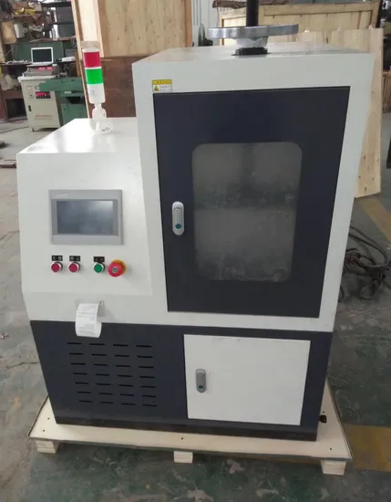
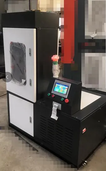
The TPJ-W10 universal dynamic and static testing bench for telescopic shock absorbers is mainly used for dynamic and static tests on telescopic shock absorbers used in cars, special vehicles, armored vehicles, electric vehicles, motorcycles, and other motor vehicles, including dynamism, speed, fatigue life, damping, and friction tests. It is a high-performance testing machine with a high cost-performance ratio. The machine features a reasonable, simple, and reliable structure; accurate and convenient adjustment of the test space and test stroke; convenient and reliable specimen clamping; stable operation; and easy maintenance.
The maximum speed of the shock absorber’s dynamism indicator is 1.04 m/s; speed parameters below this speed can be set arbitrarily.
2. Scheme Description
2-1. Main Unit
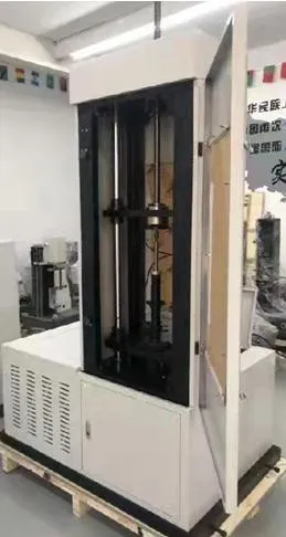
The main unit mainly consists of four parts: frame, mechanical loading mechanism, transmission mechanism, and fixtures. The frame comprises a column, worktable, vibration table, upper crossbeam, lead screw lifting mechanism, and base. The column, worktable, vibration table, upper crossbeam, and lead screw lifting mechanism are assembled together and stably mounted on the base. The damper under test is installed between the vibration table and the worktable via fixtures. The amplitude is adjusted to meet the requirements of specimens of different sizes and specifications. By changing the fixtures, the requirements of specimens with different installation methods can be met.
2-2. Loading Mechanism
The dynamic loading part consists of a crank-connecting rod mechanism, which converts the rotational motion of the motor into linear reciprocating motion in the vertical direction. By adjusting the eccentricity of the slider, the distance of the linear reciprocating motion can be adjusted to achieve the required test stroke of the test specimen.
The spatial adjustment part mainly consists of a motor, lead screw, and guide mechanism, completing the static part of the test.
2-3. Transmission System
Dynamic Components: The transmission mechanism consists of a CNC motor, a V-belt, and a flywheel. The fatigue test speed can be adjusted arbitrarily within the allowable range by regulating the motor speed.
2-4. Test Fixture
The test fixture is specially designed and manufactured according to the structure of the specimen, i.e., the shock absorber. It is generally fixed using pins or screws.
2-5. Sensor:
5.1 Force sensor (DC): Range 卤10kN, filtration capacity 150%. Placed at the front end of the actuator.
5.2 The sensor is calibrated before leaving the factory.
2-6. Main Features:
6.1 The amplitude and frequency of the vibration damper fatigue test are freely adjustable.
6.2 Digital display of vibration frequency and number of vibrations; generates sinusoidal curves of force and time, making force attenuation clear at a glance.
6.3 Automatic shutdown after preset test cycles, resulting in higher efficiency.
6.4 Fully automatic control for performance testing: fully automatic fixtures and one-button fully automatic testing. Improves testing efficiency and reduces testing costs.
Simultaneous display of performance curves and velocity curves. Can test 5 segments of compression force; each segment can be set automatically or manually via buttons, completing the test in one go and generating performance and velocity curve graphs for convenience and speed.
6.5 Wide testing range: Capable of testing shock absorbers with large stroke (100mm) and long length (1000mm), as well as those with small stroke (20mm) and short length (180mm), meeting testing requirements at all locations without dead spots.
6.6 Test results are automatically differentiated by color (green for pass, red for fail), providing a clear and quick assessment.
6.7 Controller and software are independently developed and can be customized to meet individual customer requirements for fast and accurate testing.
3. Fully Digital Electro-hydraulic Controller:
3-1. Main Components of the Fully Digital Controller:
1.1 Computer (Business PC, 19″ LCD monitor, Windows operating system)
1.2 Two-channel signal conditioning unit (test force, displacement, and indicator curve)
1.3 Other necessary I/O input/output units
1.4 Dynamic testing software and dedicated data processing software for shock absorber testing
3-2. Main Technical Specifications of the Controller: Fully digital hydraulic servo controller based on PCI bus
2.1 Control method: Fully digital PID closed-loop control for force, displacement, and deformation; control modes can be smoothly switched.
2.2 Main test waveform: Sine wave;
2.3 Test signal measurement resolution: 鈮?/200000, indication accuracy 0.05FS
3-3. Software Testing System:
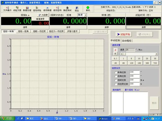
fatigue test curve
3.1 Windows operating system with a fully Chinese user interface;
3.2 Employs high-speed data acquisition technology to achieve high-speed data acquisition across multiple channels;
3.3 The computer screen displays test curves and various test parameters, such as force/displacement-time curves, force-displacement curves (dynamometer diagrams), and peak and valley values of test parameters (force, displacement);
3.4 The system has complete file operation functions for storing test curves and test data; simultaneously, test data can be stored in ASCII format, allowing users to perform secondary data processing using commercial data processing software;
3.5 Supports printing test reports;
4. Main technical specifications of the testing machine:
NO. Project Content Technical parameters
1 Maximum test force (tensile, compressive) 10KN
2 Fatigue test frequency 0.5~5Hz
3 Test amplitude 卤50mm (stroke 100mm)
4 Maximum linear velocity in demonstration test 1.04m/s
5 Sensor calibration accuracy 1%FS
6 Counter capacity 9*10^9
7 Counting stop accuracy 卤1
8 Maximum outer diameter of specimen 桅150mm (custom fixture design available)
9 Shock absorber mounting position 1 piece
10 Maximum specimen length 1000mm (customizable)
11 Power supply voltage (three-wire four-phase) 380VAC 50Hz
12 Motor power 11 kW
13 Electrical equipment quality, assembly quality, and appearance quality of the testing machine Should comply with GB/T2611-2006 “General Technical Requirements for Testing Machines”
5. Testing machine configuration
NO. Item Name Spec. Qty
1 Main frame Self-made 1 SET
2 Main load motor Lu Chen 1 SET
3 Electrical control cabinet Self-made 1 SET
4 Inverter Yi Neng 1 SET
5 Load sensor Da Yang 1 SET
6 Controller Independently developed 1 SET
7 Controller system software Independently developed 1 SET
8 Computer HP 1 SET
9 Printer HP LVDT 1 SET
10 Displacement sensor Instruction manual, certificate of conformity, packing list 1 SET
11 Random documentation Self-made Each 1 copy
5. Operating Conditions of the Testing Machine
5-1. Ambient temperature: 10掳C-35掳C; Relative humidity: 鈮?0%
5-2. Horizontal installation on a stable foundation, with a levelness of 0.2/1000;
5-3. Environment free from vibration, corrosive media, and strong electromagnetic interference.
5-4. Power supply voltage fluctuation: not exceeding 10% of the rated voltage;
5-5. The equipment should be at least 0.8m away from walls on both sides for easy maintenance.
6. Delivery Time: Within 25-35 days from the date of contract signing and advance payment.
7. Installation, Commissioning, Acceptance, and Personnel Training
7-1. Installation and Commissioning: The supplier is responsible for the transportation of the equipment at its own expense. Upon arrival, the buyer is responsible for unloading, unpacking, and positioning the equipment at its own expense. After the buyer positions the equipment, the supplier is responsible for wiring and commissioning. The buyer should provide necessary assistance to the supplier’s commissioning personnel during commissioning
Technical Specifications
| NO. | Project Content Technical parameters |
| 1 | Maximum test force (tensile, compressive) 10KN |
| 2 | Fatigue test frequency 0.5~5Hz |
| 3 | Test amplitude 卤50mm (stroke 100mm) |
| 4 | Maximum linear velocity in demonstration test 1.04m/s |
| 5 | Sensor calibration accuracy 1%FS |
| 6 | Counter capacity 9*10^9 |
| 7 | Counting stop accuracy 卤1 |
| 8 | Maximum outer diameter of specimen 桅150mm (custom fixture design available) |
| 9 | Shock absorber mounting position 1 piece |
| 10 | Maximum specimen length 1000mm (customizable) |
| 11 | Power supply voltage (three-wire four-phase) 380VAC 50Hz |
| 12 | Motor power 11 kW |
| 13 | Electrical equipment quality, assembly quality, and appearance quality of the testing machine Should comply with GB/T2611-2006 “General Technical Requirements for Testing Machines” |
| NO. | Item Name Spec. Qty |
| 1 | Main frame Self-made 1 SET |
| 2 | Main load motor Lu Chen 1 SET |
| 3 | Electrical control cabinet Self-made 1 SET |
| 4 | Inverter Yi Neng 1 SET |
| 5 | Load sensor Da Yang 1 SET |
| 6 | Controller Independently developed 1 SET |
| 7 | Controller system software Independently developed 1 SET |
| 8 | Computer HP 1 SET |
| 9 | Printer HP LVDT 1 SET |
| 10 | Displacement sensor Instruction manual, certificate of conformity, packing list 1 SET |
| 11 | Random documentation Self-made Each 1 copy |
More Photos