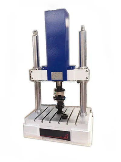
Resonance Fatigue Testing Machine (Electromagnetic High-Frequency)
Fatigue Testing Machines
Overview
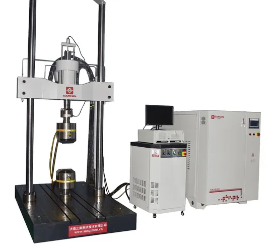
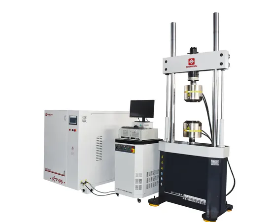
The CHENJI resonance fatigue testing machine is an electromagnetic high-frequency resonance type machine designed to determine the fatigue limit, fatigue life and S-N behaviour of metals, alloy materials and their components under tension, compression or tension-compression alternating loads at room temperature. Typical specimens include fasteners, connecting rods, operating joints and screw moving parts, so the machine is used wherever a component must survive many millions of load cycles rather than a single overload.
Because the machine is based on the electromagnetic resonance principle, it drives the specimen into resonance with small power consumption and reaches a very high testing frequency of 50-250 Hz. That frequency is what makes a high-cycle fatigue test practical: a test that would take weeks on a slow servo-hydraulic frame can be completed in days or hours. With the corresponding test fixtures the same machine performs three-point bending, four-point bending, thin-plate tension, thick-plate tension, reinforced-steel tension, chain tension, fastener, connecting-rod, torsional fatigue, bending-torsion composite fatigue and alternating-bending fatigue tests, as well as CT/CCT and gear fatigue tests.
Technical Specifications
| Parameter | Value |
|---|---|
| Model series | PLG-20C / 50C / 100C / 200C / 300C / 500C |
| Static load | 20 / 50 / 100 / 200 / 300 / 500 kN |
| Dynamic peak load | +/-10 / +/-25 / +/-50 / +/-100 / +/-150 / +/-250 kN |
| Measuring range | 1%-100% FS |
| Load accuracy | Static +/-0.5%, dynamic +/-1% |
| Frequency | 50-250 Hz (resonance) |
| Gripping distance | 500-700 mm |
| Column distance | 450-600 mm |
| Power supply | AC 220V +/-10%, 50 Hz |
| Standards | GB/T 3075, ISO 1099 (axial force control fatigue testing) |
Electromagnetic resonance principle
The machine excites the specimen into resonance so that the mechanical energy stored in the elastic system supplies most of the cyclic load, and the electromagnetic exciter only has to replace the energy that is damped out each cycle. This is why the power consumption is small compared with the load amplitude delivered, and why the testing frequency can be far higher than on a conventional fatigue frame. The static load is superimposed on the alternating load so that a mean stress can be held constant while the cyclic amplitude is applied.
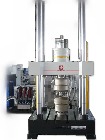
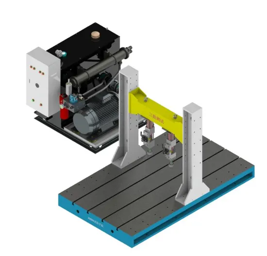
Constructed with a rigid frame, an electromagnetic exciter and a digital control system, the machine provides accurate static and dynamic load control and excellent stability during long-duration high-cycle fatigue tests. Because the frame must not absorb the vibration it is built stiff and heavy, and the digital controller keeps the resonance condition stable as the specimen stiffness changes during the test.
Fatigue methods and fixtures
With the appropriate fixtures the machine covers the full range of resonance fatigue methods required by industry: axial tension-compression on round and flat specimens, three-point and four-point bending, thin-plate and thick-plate tension, reinforced-steel tension, chain tension, fastener and connecting-rod testing, torsional fatigue, bending-torsion composite fatigue and alternating-bending fatigue. CT and CCT specimens for fatigue-crack-growth work and gear fatigue testing can also be run.
The standard specimen geometry, the test speed and the number of cycles to failure follow the applicable standard. The machine is normally used to GB/T 3075 and ISO 1099 for axial force controlled fatigue testing, and the S-N curve is built from a series of specimens run at different stress amplitudes.
Applications and industries
The resonance fatigue testing machine is widely used in aviation, automobile, machinery, railway, construction and material research laboratories. In aviation and railway work the machine qualifies safety-critical fasteners and structural parts; in the automobile industry it is used for connecting rods, springs, joints and suspension components; in machinery and construction it supports the fatigue design of screw moving parts and steel reinforcement. Whichever the industry, the purpose is the same: to know how many cycles a component survives at a given stress, so that the design lives can be validated before the part is put into service.
Frequently Asked Questions
What is the testing frequency of the machine?
The machine runs at 50-250 Hz in resonance, which is much higher than a conventional servo-hydraulic fatigue frame and makes long high-cycle tests practical.
What load capacities are available?
The PLG series is supplied with static loads of 20, 50, 100, 200, 300 and 500 kN, with matching dynamic peak loads from +/-10 kN up to +/-250 kN.
Which tests can it perform besides axial fatigue?
With the correct fixtures it performs three-point and four-point bending, thin-plate and thick-plate tension, reinforced-steel tension, chain tension, fastener, connecting-rod, torsional, bending-torsion composite and alternating-bending fatigue tests, as well as CT/CCT and gear fatigue tests.
Which standards does it test to?
It is designed for GB/T 3075 and ISO 1099, which govern fatigue testing under axial force control.
What accuracy does the load measurement achieve?
Static load accuracy is +/-0.5% and dynamic load accuracy is +/-1%, over a measuring range of 1%-100% FS.
Related Products & Pages
- Fatigue Testing Machines
- 300/500/1000/3000 kN Computer Control Electro-Hydraulic Fatigue Testing Machine
- Torsion Testing Machines
- Metal Testing
About CHENJI & Support
CHENJI is the brand of Jinan Chenji International Trade Co., Ltd. (Shandong, China), a manufacturer and exporter of material testing machines since 2014, with in-house quality control plus third-party inspection by SGS or Bureau Veritas. The company holds ISO 9001 certification (626024QH073R1) and is a Bureau Veritas audited supplier (MIC-ASR2451820). Testing machines are normally supplied with a calibration certificate valid for 12 months and traceable to national force standards, and our engineers help you select the machine, fixtures and accessories for your specimen and method.
Every quotation is prepared against the standard you test to, so the delivered machine matches the test method rather than only the headline capacity. Spare parts, consumables and calibration support are available after delivery, and machines can be produced to OEM or ODM requirements when a customer drawing or specification is provided.
Selecting and Verifying a Testing Machine
Choosing a machine is a matter of matching capacity to the specimen and the method, not of buying the largest frame. Capacity selection follows the specimen and the standard, and the force measuring system should be verified per ISO 7500-1 or ASTM E4 on a regular schedule. Load cells are commonly supplied as class 0.5 or class 1, which means the indicated force stays within ±0.5% or ±1% of the true force.
Test results are only comparable when they are quoted together with the standard, the specimen geometry, the test speed and the force measurement class. We are glad to review your test method and specimen so that the machine, fixtures and accessories are correctly specified before you order.
Request a Quotation
Tell CHENJI the component, the stress amplitude and the standard you test to, and we will recommend the correct PLG model, the fixtures and the fatigue-test software for a quotation.
Email annie@chenjitester.com or call / WhatsApp +86 158 5311 1612.
More Photos