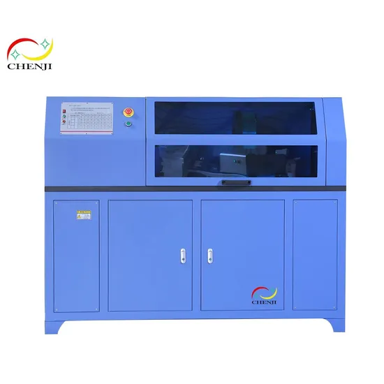
M10-M20 Bolt Friction Coefficient Tester Bolt Testing Equipment High-Strength Bolt Tester Intelligent Detection of Torque/Axial Force/Friction Coefficient
Bolt & Fastener Testing
Overview
Microcomputer Controlled Fully Automatic thread Analysis and Testing System
Functional Overview
The NCMC-2000SE microcomputer-controlled fully automatic thread analysis and testing system is a thread analysis system jointly developed by our company under the commission of the Fastener Industry Association. It is mainly used for testing and analyzing threaded fasteners. At present, all test data have been recognized by metrology agencies, testing agencies, and bolt manufacturers.
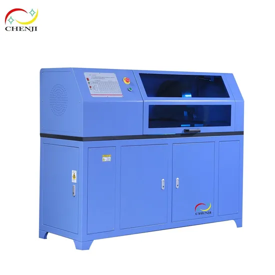
The floor-standing cabinet structure designed according to human mechanics is convenient for experimental personnel to load and unload the test pieces;
The testing machine is mainly used for testing axial force (clamping force), total torque, preload, thread torque, support surface torque, total friction coefficient, support surface friction coefficient, thread friction coefficient, K coefficient, yield limit torque and axial force, breaking torque axial force, tightening angle, etc.
It can realize tests such as equal rate loading and equal rate torsion angle, and can control torque and horn in sections in one test, and can smoothly switch between controls.
The test parameters are collected by computer and processed by software, which can automatically control the test process and automatically obtain the test results. The test curve and test results are displayed in real time on the microcomputer screen, and the test report and test curve can be printed.
Independent research and development of software, measurement and control systems, and hardware has broken the reliance on imported equipment.
4. Functional modular design
4-1. Effective torque test—-ISO2320-2008, tightening characteristics of locking nuts
4-2. Friction coefficient test—-ISO16047, GB/T16823
4-3. Simulated working condition test—-verify assembly effectiveness according to different assembly process programming of customers
4-4. Attenuation detection——-delay detection of axial force attenuation curve
4-5. Yield tightening test—-assembly torque and axial force required to detect yield point
4-6. Tightening damage test—-detect axial force and torque of fastener damage
4-7. Its compliance standard reference: ISO16047, GB/T 3098.9-2010, GB/T16823.3-2010, ISO 2320, ISO 261
5. Equipment parameters
5-1. Total tightening torque measurement range: 2000N.m;
5-2. Axial force clamping force: 350KN;
5-3, thread torque: 1000N.M;
5-4, torque measurement accuracy: 卤1%;
5-5, torsion angle measurement resolution: 0.001掳;
5-6, torsion angle measurement accuracy: 卤1%;
5-7, loading speed: 0 ~ 1500掳/min;
5-8, clamping load accuracy: 卤1%;
5-9, data acquisition card acquisition rate: >1KHZ/S;
5-10, torsion direction: positive and negative directions;
5-11, power supply: 2.5KW, three-phase AC 380V;
5-12, sample test space: 800mm;
5-13, power supply: 380V/50Hz;
5-14, weight: about 1500kg.
6. Equipment configuration
6-1. One 2000Nm test machine host (including one set of protective cover);
6-2. One 2000Nm flange type dynamic total torque sensor (German NCTE or with the same accuracy level);
6-3. One 1000Nm/350KN compression and torsion composite sensor (AVIC Research Institute or with the same accuracy level);
6-4. One set of NAICE TEST high-precision digital measurement and control system (NAICE);
6-5. One set of NAICE TEST special measurement and control software (NAICE);
6-6. One AC servo motor (imported from Japan);
6-7. One set of AC servo drive (imported from Japan);
6-8. One set of special bolt fixture (NAICE);
6-9. One set of commercial computers;
6-10. One set of random tools (special tools for jaw replacement);
7. Equipment Details
7.1. Introduction to the main machine
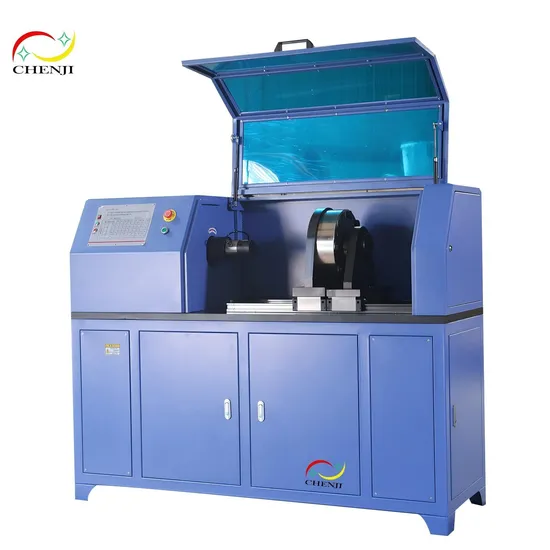
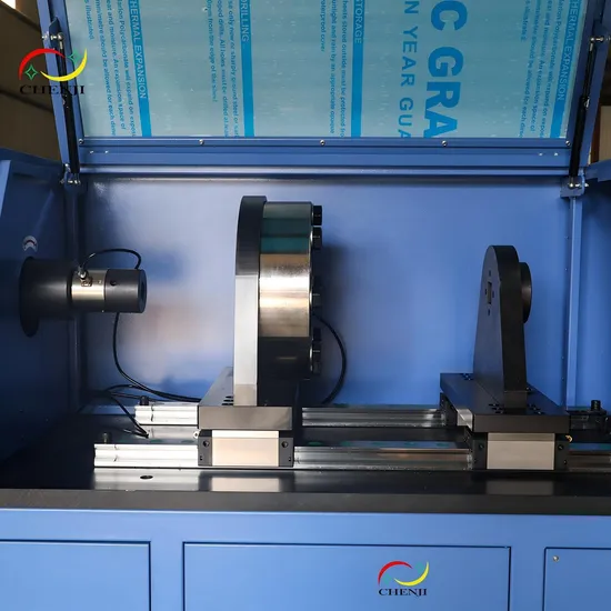
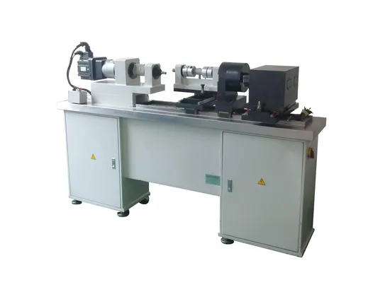
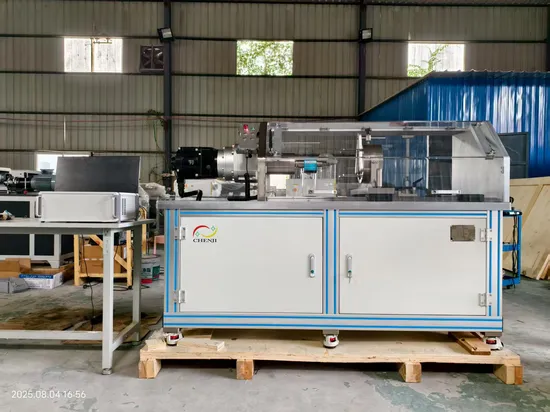
The machine consists of a working platform, a servo motor and reducer imported from Japan, a high-precision dynamic torque sensor, a load sensor, a fixture, a static torque sensor, and a guide rail.
The loading mechanism uses a servo motor to drive the reducer to apply torque to the sample. The torque value and clamping load of the sample are measured by the sensor. At the same time, the torsion angle is detected by the photoelectric encoder. The detected signal is transmitted to the measurement control system to complete the measurement of the sample torsion index and the drawing of the curve.
-Safety load: 150% rated load;
-Excellent linearity under forward and reverse load, linear error 0.3% FS;
-Dynamic load accuracy is 0.3% of indicated load.
-The flange sensor itself has a concentric design structure.
-The flange torque sensor is much shorter than the shaft torque sensor, so it is less affected by its own weight
7.2 Controller Introduction
The electrical core is the NAICE TEST controller specially used for the test machine by our company. It is a controller developed based on DSP test technology to meet the GB/T228.1-2010 test. It has full digital control, multi-channel acquisition and other functions. The system is powerful, accurate in data processing, simple to operate, and easy to use and maintain.
NAICE TEST controller performance features:
1. NAICE TEST uses FPGA chip, embedded with customized ARM core, full-path parallel operation, and achieves the computing workload of a single-core CPU above 1GHz with a 100MHz computing clock speed. External communication uses 100M adaptive Ethernet TCP/IP protocol with RJ45 interface. It has strong anti-interference ability, long-term stable operation, and fast closed-loop speed.
2. NAICE TEST integrates data acquisition, closed-loop control, and I/O operation, and can be applied to dynamic testing machines with closed-loop control requirements. It can be directly connected to the host computer software through high-speed Ethernet. It is widely used in various test instruments that require high-speed acquisition and control, such as automotive fatigue, fastener analysis, conventional fatigue, lateral vibration, and electro-hydraulic servo.
3. NAICE TEST is a true multi-task parallel processing system. It uses FPGA to parallel and synchronously process all closed-loop control data, which can ensure that the system has high response speed, high control accuracy, smooth control switching, accurate data acquisition and synchronization.
4. NAICE TEST displays the PID closed-loop adjustment effect on the debugging software with a curve graph, and intuitively sees the adjustment effect of the PID parameters. During closed-loop control adjustment, the control effect curve after changing the PID parameters is displayed on the debugging software, making PID adjustment real and simple.
5. Maximum 6-way +-10v analog input interface, internally using high-precision, high-speed AD, can simultaneously collect a maximum of 6 load sensors, electronic extensometers, torque sensors, pressure sensors, temperature and other signals in parallel.
6. 8-way 422 differential signal input, can simultaneously collect 4-way differential pulse encoders, grating rulers, binary SSI or Gray code magnetostrictive sensors and other signals in parallel.
7. 8-way differential pulse output signal, can pulse output control servo motors and other drivers.
8. 3-way 16-bit DA signal output, the interface has been adjusted to +-10V output, can directly control MOOG voltage-type servo valves and other types of voltage-type servo valves, proportional valves, or drive current-type servo valves through external voltage-to-current modules.
9. 16-way fully isolated transistor output interface, which can drive the relay to control various switch valves or indicator lights on the periphery of the test machine.
10. 16-way fully isolated switch input interface, which can directly connect emergency stop, button, and light-on signal input.
11. 7 Communication interface RJ45 Ethernet interface.
Software introduction
1. Modular design: NAICE TEST adopts modular design, dividing the software into several modules for easy upgrade and authority management.
2. Diversified upgrade methods: NA
More Photos